Written by Gary WA2JQZ, October 2014.
At our October monthly meeting in 2014, we were treated to an excellent talk about Hexagonal Beam antennas, or Hex Beams, by Rob Conklin N4WGY. Rob is a local ham, a mechanical engineer, and a home brewer. He introduced to us what the Hex Beams are, how they perform, and how they are constructed. And he shared his home brewing experience of building one for himself. He showed us how relatively easy they are to build. It was such a good talk, and a good source of information, that I would like to highlight what he shared.
These are some attractive characteristics of the Hex Beam.
- They are relatively low-cost directional antennas compared to the regular multiband Yagis, and don’t require large towers.
- Compared to the regular Yagis, their profile provides lower wind loading, and they are relatively more stealthy.
- They are relatively light weight (~25 lbs) and small (~22 feet diameter).
- They perform well. Their gain and front/back ratio are comparable to the regular 2-element Yagis. They will work well if just above the roof. They are typically HF, and for HF many of the measurements don’t require tight tolerances. They have about a 3 dbi gain over dipoles.
- You can buy commercially made Hex Beams.
- But they also are very conductive to home brewing. Good selections of commercial parts and kits are available. You don’t need fancy tools nor a lot of skill.
- You can get up to 6 bands without traps and without a tuner. They are relatively easy to adjust.
Hex Beam Design
When I first saw Hex Beam antennas, I was confused because I couldn’t immediately distinguish what their many elements were for. But actually their basic plan is simple.
If it is a monoband antenna, it is just a 2-element wire Yagi system, with a driver and reflector. The wires are supported by what looks like an upside-down umbrella structure. The structure consists of 6 spreader arms mounted radially from a central base-plate, and a straight center post also mounted from the base-plate. The wires mostly follow the spreader arms’ hexagonal shape. The driven element wires are supported by one half of the upside-down umbrella, the reflector is supported by the other half. The spreader arms are structurally supported at their open ends by Dacron tension cords connected to the top of the central post. Two Dacron cords also run between two spreader arms on the front driver side of the antenna, to maintain correct separation. The central post contains a 50 ohm coax feed. A mast mounted to the bottom of the base-plate can be rotated to direct the antenna.
Hex Beams are often multi-band antennas, with up to 6 bands. The multi-band antennas have individual 2-element wire Yagi systems for each band, stacked as you go higher up the umbrella. The 6-band Hex Beam that Rob built operates 6, 10, 12, 15, 17, and 20 meters. The shorter wavelength 6 meters antenna wires are the lowest, where the distance between spreader arms is least. 20 meters wires are the highest.
And so unlike the regular Yagis which use trap coils to operate on multiple bands, the Hex Beam design just utilizes separate wire sets for each band.
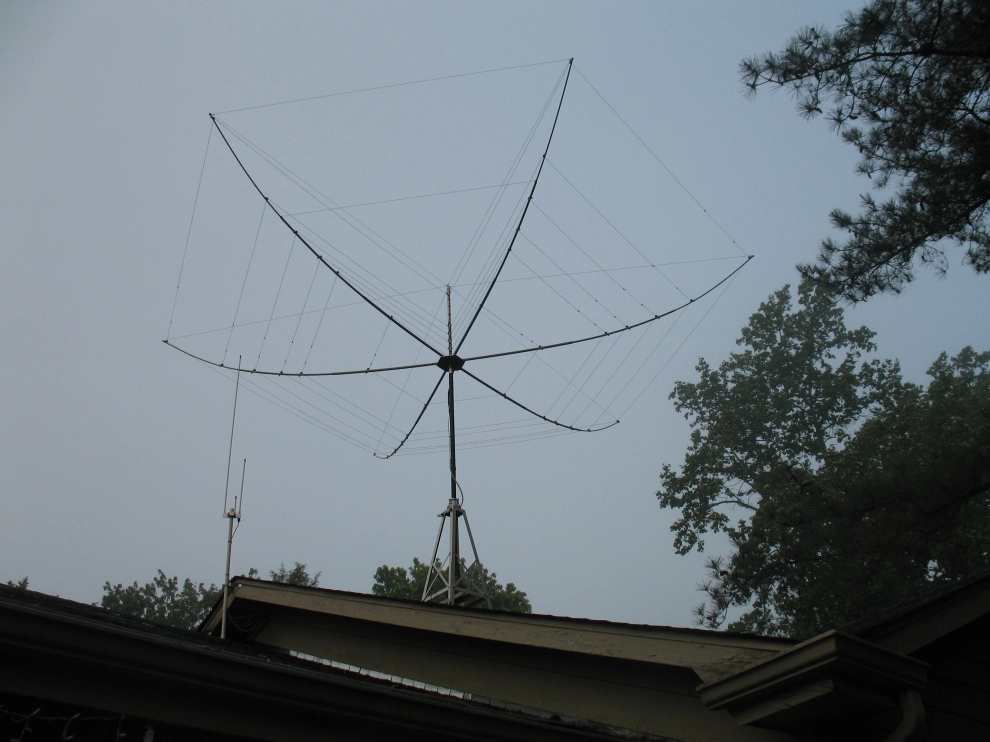
This is Rob’s antenna on the roof at his home.
 Hex beam antenna on Rob’s roof. The front driven element side is facing us. Click to enlarge, click “back” on your browser to return. [Courtesy N4WGY]Classic and G3TXQ Hex Beam Versions
Rob discussed two designs of the Hex Beam. The original classic version was manufactured by Traffie Technologies, and then copied by many home brewers. Rob said many hams use it and swear by it. But it has two performance shortcomings. First, it is narrow banded; that is, if you tuned the antenna length for the SSB portion of the band, its SWR might be too high at the CW end. Second, if front/back selectivity is peaked, the SWR is no longer optimized. And so that front/back selectivity had to be compromised.
The shortcomings were overcome in 2007 by Steve Hunt G3TXQ. After extensive modeling and experimenting, he developed a modified design that corrected both problems and gave the hex beam better performance: The G3TXQ design has good SWR across the full ham bands. And the peak front/back ratio is at the optimal SWR. With a slightly simpler wire system, it is also is a little easier to build. Rob built a K4KIO version of the G3GTX design.
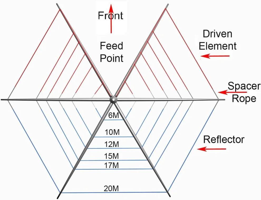
In both the original and G3TXQ designs, the layout of the driven element wires is similar. The driven element layout is shaped like an “M”, or more precisely like two “V”s. One end of each “V” starts from the feed connection at the central post, extends to a spreader arm, then continues as a side of the hexagon to the next spreader arm. Spacer ropes clamped at the spreader arms keep the wires in sufficient tension.
 Schematic top view of G3TXQ Hexbeam antenna. [Courtesy N4WGY]
The other end of the spacer ropes connect to the reflector wires. The spacer ropes keep a critical separation distance between the driver and reflector elements. The lengths of the wire elements and the spacer ropes are the critical measurements to make for the hex beam.
In the original design, the reflector wires had also followed an “M” shape configuration. In the G3TXQ design, however, the reflector wires follow the hexagonal shape provided by the spreader arms.
Performance
As Rob points out, the G3TXQ design provides good SWR performance across the full range of each ham band. He showed us a spectrum analysis of his antenna.
![Full SWR scan of N4WGY's hexbeam antenna, from 1 to 36 MHz (160 to 10 meters ham bands). [Courtesy N4WGY]](https://wa4nzd.files.wordpress.com/2014/10/160-10swrscan_n4wgy_hexbeam.jpg?w=990&h=691) Full SWR scan of N4WGY’s hex beam antenna, from 1 to 36 MHz (160 to 10 meters ham bands). The grey columns are the ham bands. Note the SWR dips where this hex beam is designed for: 20, 17, 15, 12, and 10 meters. The antenna is also resonant for 6 meters (50 MHz), but the analyzer doesn’t reach that high a frequency. [Courtesy N4WGY]The chart shows the SWR performance of his Hex Beam, as the frequency varies from 1 MHz at left to 36 MHz at right. The shaded columns are the locations of the amateur radio bands. For the bands not designed for, 160, 80, 40, and 30 meters at left, the SWR values are well above 3:1. But at 20 meters the SWR dips to about 1.2:1 and is well below 2:1 across that band. The SWR for the other ham bands designed for also remain below 2:1 and in some cases also dip to as low as 1.2:1. You can click the image to see the details for each band. You can see Rob made his lengths slightly long, but he can adjust that, to better position the dips within the ham bands.
Full SWR scan of N4WGY’s hex beam antenna, from 1 to 36 MHz (160 to 10 meters ham bands). The grey columns are the ham bands. Note the SWR dips where this hex beam is designed for: 20, 17, 15, 12, and 10 meters. The antenna is also resonant for 6 meters (50 MHz), but the analyzer doesn’t reach that high a frequency. [Courtesy N4WGY]The chart shows the SWR performance of his Hex Beam, as the frequency varies from 1 MHz at left to 36 MHz at right. The shaded columns are the locations of the amateur radio bands. For the bands not designed for, 160, 80, 40, and 30 meters at left, the SWR values are well above 3:1. But at 20 meters the SWR dips to about 1.2:1 and is well below 2:1 across that band. The SWR for the other ham bands designed for also remain below 2:1 and in some cases also dip to as low as 1.2:1. You can click the image to see the details for each band. You can see Rob made his lengths slightly long, but he can adjust that, to better position the dips within the ham bands.
Rob brought in to show us the antenna analyzer he used to scan his antenna and make the chart. This analyzer connects through a USB cable to a computer, where the scans can be displayed, zoomed in for details, and saved. The analyzer is made in India as a kit and costs under $60. The analyzer is called a Fox Delta AAZ-0914A. http://www.foxdelta.com/products/aaz-0914a.htm.
Rob mentioned that he can reliably make contacts around the world, when propagation permits. And he feels comfortable competing with hams with larger antenna systems.
Construction Tips
![Rob Conklin N4WGY presenting at our meeting [Photo courtesy NM4T]](https://wa4nzd.files.wordpress.com/2014/10/rob-hex-beam-presentation_2.jpg?w=990&h=743) Rob Conklin N4WGY presenting at our meeting, here discussing construction details. [Photo courtesy NM4T]Rob devoted much of his talk to construction details, and much of the Q&A from the group was about components and building. I will mostly defer to the online resources Rob suggested. But Rob did give some additional advice:
Rob Conklin N4WGY presenting at our meeting, here discussing construction details. [Photo courtesy NM4T]Rob devoted much of his talk to construction details, and much of the Q&A from the group was about components and building. I will mostly defer to the online resources Rob suggested. But Rob did give some additional advice:
- Don’t use PVC for the center post. Especially in the South with UV from sunlight, the material will quickly degrade. Spend the extra money to get UV resistant tubes. He recommends buying online the mast sold by K4KIO.
- For the wire sets, he says 14 AWG stranded/plated and uninsulated antenna wire would be best.
- Telescoping fiberglass poles are recommended for the spreader arms.
- Do not make the wire elements too tight.
Here are resource links.
Construction plans:
- http://www.hex-beam.com/ – The K4KIO website with detailed, step-by-step construction plans, similar to what Rob showed us.
Supplies and commercial hex beam kits:
SWR scanner tool:
Addendum
For the close of the talk, Craig Behrens NM4T brought in to show us a light-weight, self-contained, portable G3TXQ hex beam antenna. It is designed and manufactured by a company in Germany called Folding Antennas. The antenna weighs only 9 pounds, is collapsable to 45 inches, and comes in an easy-to-carry bag. Instead of folding out like an upside-down umbrella, the spreader arms fold out flat. The flat configuration has much less bending load, and therefore the spreaders are made thinner and lighter. The wires have special fittings to attach to the poles. The antenna can be assembled by one person in 10 minutes. [See http://www.vibroplex.com/contents/en-us/d3.html. ]
Craig also showed us a prototype TenTech Patriot QRP transceiver. It operates SSB, CW, and digital modes on 20 and 40 meters at 10 Watts. Its design was influenced from recommendations by his QRP Skunkwerks group. During the following week Rob Suggs KB5EZ (one of the members of that group) gave it some field testing.
The club again thanks Rob Conklin N4WGY for giving us an excellent practical, educational presentation. The club also thanks Craig Behrens NM4T. And thanks to our members and guests for participating.
One of the eQSLs the club recently received shows a hex beam of KL2R, the Two Rivers Contest Club in Fairbanks, Alaska. You can see the wires in front of the aurora.
 QSL card we received from KL2R in Fairbanks, Alaska, showing their hex beam at night (with aurora).
